
NOTE I have created a new post detailing how to configure the sand bot once you have it running. So after reading this, if you have questions, please see my new post.
I have also created a forum for Sand Table Questions and Answers here: http://alwaystinkering.com/forums/forum/diy-sand-table/ – I figure this will be easier to read than the condensed comments section under the post.
I forget exactly how, but one day browsing the internet I came across the kickstarter for the sisyphus table, and was blown away. This is the first time I had seen something so captivating that I immediately wanted one. Checking their page, I was disheartened by the prices of the full wooden coffee tables, but I still considered it. I decided to try and see if anyone had built a DIY version of this table that I could perhaps take on myself before dropping thousands of dollars.
Eventually I stumbled upon a UK Engineer named Rob Dobson’s personal blog page. He had created a smaller version of with a similar mechanism. This looked promising. I saw he re-designed his whole bot and the mechanism to a new SCARA type robot. He had the 3D model and all the stl files ready for 3D printing, so I decided to start my journey of creating my own table from these plans.
As a side note – during my research I learned about all the CoreXY tables that have been doing similar things for years. I stumbled across the very nifty Sandify tool as well, which generates pattern gcode. I entertained the idea of a CoreXY table, but I had my mind set on a round coffee table after seeing the beautiful sisyphus tables, so the XY machines just wouldn’t fit my needs.
Rob’s blog gives a good idea of how to go about assembling everything, so I will just go over my differences here.
I don’t have a laser cutter – so I decided to 3D print everything out, not just the 3D printed parts.
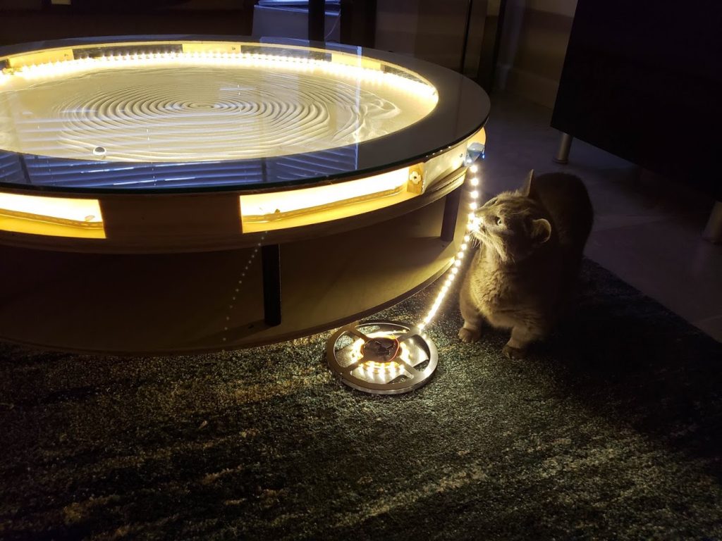
I think the easiest think to do here is link my build album, because it shows the progress of the build. I wanted to build an actual piece of furniture for this table, to sit in our sitting room, so it had to look nice.
Some highlights
First working protoype of the robot
Table Design.. on the fly!

LED circuit design

Initial App development (Still under development….)

Close to final table design

Inspections
3D printed LED holders

Veneer Glue-up.. ugh

Final Assembly

Neoprene only – no sand

First Run! Spreading out the sand

Complete

Some takeaways..
Furniture Building
Building a round table is hard! I used 2.5mm underlayment plywood cut into strips to build the round structure around my table frame. Using ratchet straps, I was able to clamp the wood good enough to make a decent structure. I then decided to glue maple veneer on the outside of the table for finishing. This was a nightmare. Trying to use ratchet straps on the veneer just created a whole new set of problems with bubbling because the veneer is so thin. It’s not really noticeable, but in my final table, there are noticeable bubbles in the veneer. Oh well.
Sand
I tried many different types of material for the “sand”. After researching for a while I couldn’t find any specific link to anything that I could actually buy. Some people recommended shuffleboard wax.. Some people said baking powder.. I tried them all. I finally settled on the hamster bathing sand. This is the finest sand I could find, while still able to maintain the peaks needed for nice shadows

THR Support
With some coaxing, I was able to get Rob to add support for .thr files (Theta Rho), which are the native files for the sisyphus table, so now we can take advantage of the sisyphus pattern designer’s hard work and use these patterns on this custom table. There are still some kinks with thr support, but the majority of the files work correctly and look great! The sisyphus subreddit is a great place to find custom files.
Here is my table drawing the hosta pattern from that subreddit

Micro SD Card Support
Rob and I worked hard on this, and in the end the only thing we could get to actually work was the Adalogger feather wing with SD Card in it. We tried external card readers (My PCB is wired for one), but couldn’t get anything to work reliably. Even with the feather wing, I had serious problems getting it to recognize a micro sd card. I had to try about 5 before I could finally get a 1GB micro SD card to be recognized. I used the official SD card formatter app in windows and various filesystems before this was successful. I think working SD card support is vital for having an interesting table. Without it you can only store a few smaller thr files, however you can fit many parametric patterns.

Micro SD Card Update (June 18, 2020)
In my original post I forgot a few things to make the SD card work with my PCB and robot configuration. By default, the adalogger wing has the chip select (SDCS) pin hard wired to pin 33. In my configuration, the little jumper needs to be scraped away, and a wire jumper soldered to pin 21.

When I said I could only get one SD card to work, this is the card I got working. It is a kingston 1GB microSD card formatted in FAT with the official SD card formatter.

Custom PCB
While Rob’s PCB does work – I found it very confusing at first. It is designed for more than one application, so I figured I would create a single purpose PCB for the sole reason of powering a sand table. The project can be found at Easy EDA, and the PCBs can be ordered through JLCPCB. My version 1.5 has everything needed for a functioning sand table and allows either RGB (Signal/+/-) LED control or White LED dimming control (- PWM). I have only used (And the firmware only supports) White dimming LEDs. The board also has a socket for a light sensor, which at some point will auto dim the LEDs. I wasn’t happy with my implementation of the dimming algorithm, so auto dimming is currently not supported in the firmware either.
Here is my custom PCB outfitted with everything but the drivers and processor. I’ve also included vias for probing and debugging if necessary.

Schematic (minus the external card reader)

PCB Components
Everything you need to purchase to populate the PCB
- Female and Male pin headers
- 2 x 1uF capacitors
- 2 x 100uF capacitors
- 5 x 3 pin JST-XH 2.54mm sockets (And matching plugs and crimping tool for the wires)
- 10 Ohm Resistor
- Switching 5V voltage converter
- FQP30N06L Mosfet (For dimming Whtie LEDs)
- 2 x TMC2100 Silent Step Stick Drivers
- Adafruit HUZZAH32 – ESP32 Feather Board
- Adalogger Feather Wing
Since my PCB has a different pinout than Rob’s, the robot configuration will be different. This is the robot configuration I use for my setup.
{
	"robotType": "SandTableScaraMatt",
	"cmdsAtStart": "",
	"webui": "SandUI",
	"evaluators": {
		"thrContinue": 0
	},
	"robotGeom": {
		"model": "SingleArmScara",
		"homing": {
			"homingSeq": "FR10;A+10000N;B-10000;#;A+5000n;B-5000;#;B+10000N;#;B+5000n;#;A=h;B=h;$",
			"maxHomingSecs": 120
		},
		"blockDistanceMM": 1,
		"allowOutOfBounds": 0,
		"stepEnablePin": "12",
		"stepEnLev": 0,
		"stepDisableSecs": 10,
		"axis0": {
			"maxSpeed": 9,
			"maxAcc": 50,
			"maxRPM": 2,
			"stepsPerRot": 9600,
			"unitsPerRot": 628.318,
			"maxVal": 185,
			"stepPin": "14",
			"dirnPin": "32",
			"endStop0": {
				"sensePin": "36",
				"actLvl": 0,
				"inputType": "INPUT_PULLUP"
			}
		},
		"axis1": {
			"maxSpeed": 9,
			"maxAcc": 50,
			"stepsPerRot": 9600,
			"unitsPerRot": 628.318,
			"maxRPM": 2,
			"maxVal": 185,
			"stepPin": "27",
			"dirnPin": "15",
			"endStop0": {
				"sensePin": "39",
				"actLvl": 0,
				"inputType": "INPUT_PULLUP"
			}
		}
	},
	"fileManager": {
		"spiffsEnabled": 1,
		"spiffsFormatIfCorrupt": 1,
		"sdEnabled": 1,
		"sdMOSI": "18",
		"sdMISO": "19",
		"sdCLK": "5",
		"sdCS": "21"
	},
	"wifiLed": {
		"hwPin": "14",
		"onLevel": 1,
		"onMs": 200,
		"shortOffMs": 200,
		"longOffMs": 750
	},
	"ledStrip": {
		"ledPin": "4",
		"sensorPin": "34"
	}
}
Robot Software
I’ve fielded a LOT of questions on how to get the software onto the robot for the first time. I’ve compiled a screen recording of all the steps necessary to load the firmware onto the Huzzah32 (I can’t be sure this would work with other micro processors)
Android App
While it is still under construction (Probably forever…) I have created an android application that can interface with the sand bot to control the robot and preview existing files on the robot. You can not create or upload patterns yet, and sequence creation/editing is not implemented yet. Feel free to improve/create pull requests! https://github.com/grammesm/SandBot-Android
Improving the Robot
After running my completely 3D printed robot for over a year, I could tell that it was getting really sloppy. Homing wasn’t consistent, and patterns weren’t ending where they should. Graciously, Rob had sent me some laser cut acrylic top and bottom plates a while back, so I got the making a second robot that would hold tighter tolerances. These were the major improvements I thought I needed.
I’ve uploaded all my 3D models for printing on my github. The SandTableScara model is a direct import of Rob’s original model, so that I could extend the arms.
Belt Tensioning
While the tensioning system Rob devised does work, I wasn’t happy with the tension I was getting on any of my belts. I don’t think the motors were secured strong enough to put enough tension on the drive belts. I believe this was due to my 3D printed plates, and the plastic just deforming over time. I devised a system of 3D printed tubes to help me ensure the new plates would be perfectly parallel to each other. These are secured with nylock nuts, so they aren’t going to be loosening up

The long arm belt was just floppy after a year of running. I think this is due to trying to tension a belt that wasn’t the correct size. After some trial and error I decided to print arms the exact length I needed in order to put the perfect amount of tension on a new belt of 488mm. I found that for my 3ft table and a bit less of drawing area, I needed new arm lengths of 184.5mm exactly to give me the perfect tension on the 488mm belt. I printed the bottom arm of near solid PLA, and the top arm of PETG to give me flex.

Magnetic End Stops
I believe my sloppy homing was due to the inconsistency of the magnets and hall effect sensors when dealing with different amounts of friction due to how much sand the ball is dragging around during homing. I decided to migrate to optical end stops, and designed and printed out a new concentric gear lock and elbow gear lock that allowed me to mount optical end stop sensors to track the rotational movement.
Best shot I could get of the concentric sensor

Elbow Sensor

New Sand Bed Surface
I originally started with a plywood sand surface, with the bottom coated with urethane and polished as smooth as I could get it. After I saw how uneven this surface was, I migrated to a piece of hardboard, with the smooth end down. I think this still provided too much friction and contributed to some of the inconsistencies.
I finally ponied up the money for a 3ft by 3ft piece of acrylic to cut a new table bed out of. This stuff isn’t cheap. I used 3/16″ acrylic, and there seems to be little sag to it. The magnets I use hold strong through it. Now I’m just waiting for a few more tests before covering it. PSA – drilling holes in acrylic cracks it a lot easier than I expected… Although milling it to shape with a double fluted spiral bit went much easier than expected with a hand router.

Magnet Friction
Initially, I used a piece of felt to decrease the friction between the magnet and wood sand base. I think this worked OK, but it needed to be better. I started now by polishing the acrylic’s underside with Optimum Hyper Polish and finished it up with some Optimum Spray Wax. Just by feel alone I could tell the surface was much smoother than stock acrylic. It felt slick to the touch
I also purchased some mouse skates to put on the magnet. I am hoping this further decreases the friction of the magnet on the acrylic bed

I had to cut these down to size so there was no lip around the skate, but I think this is working out well. Make sure there is no dirt on the skate.. otherwise it will start scratching the underside of the bed… Ask me how I know!
New Sand Bed Underlayment
The underlayment is necessary for dampening the sound the ball makes while riding over the sand. Otherwise it sounds like sand crunching all the time, which isn’t pleasant.
In my original build, I used some neoprene as sand underlayment. While this worked great, I noticed the sand seemed to be disappearing! To my surprise, neoprene is quite porous and can trap a TON of sand in the fabric itself. This provided a much harder surface full of sand to drag the ball around on. After looking at quite a few different types of fabric, I settled on buying some velvet. The soft side has a bit of pile to it, so this should dampen the sand sound pretty well.
New velvet underlayment spray glued to the acrylic bed.

Spreading the sand out with the new velvet. Pretty quiet!
Only time will tell how these new improvements hold up. We shall see!
(Incomplete) List of purchases for this project:
EasyEDA
| Qty | Product | Price | Notes |
|---|---|---|---|
| 1 | Custom Sand Table PCB | $7 |
Amazon
Hi Matt
Your sandtable post does not have a comment session so I’m hijacking this post, sorry for that 🙂
Would it be possible for you to share the CAD files of your updated table design? 3d models instead of STL would be much better so I can modify them if needed.
Cheers!
Burak
Hi Burak – I’ve enabled comments here and uploaded all my Fusion 360 models to https://github.com/grammesm/Sandbot-Models. Hope this helps!
Thanks a lot Matt!
I might be bothering you with some specifics during the build 🙂
Cheers!,
Burak
Hi Matt, Do you have a file where are the models are in position in fusion? I don’t have a 3D printer but I hope I can make the parts on my CNC. Maybe I need to do some small adjustments.. For this, it would be better to have the model like it is assembled. Can you help me please?
With kind regards
–Bram
Hi Bram. If you import Rob’s original model into fusion (3dm file), everything should be in place. https://github.com/robdobsn/SandTableDesignScara
Hi Matt. What a great design! Thanks for posting all this information! I used your design models and built one myself. I actually brought the .stl models into a cad system and changed up the models a bit as needed and 3d printed them. On the electronics side I used a Raspberry Pi controlling an arduino cnc board and shield which is VERY convenient because you can remote login to the PI and control the OS and files and all that. My biggest problem now is getting the Sandify designs to run on this scara design machine. Maybe I’m missing something and also confused. I’m attempting to write a vb program that will convert an xy pattern to the correct scara arm rotations.
Hi John.. Nice job!. Since I didn’t write any of the motion firmware for this, I’m not going to be of much help translating to rotational commands. When you say XY pattern, are you talking about sandify’s gcode export? Rob’s firmware for this robot is open source, so I can point you to his gcode interpreter that will process gcode commands and submit them to the robot’s motion manager. I hope this helps.
https://github.com/robdobsn/RBotFirmware/blob/master/PlatformIO/src/WorkManager/Evaluators/EvaluatorGCode.cpp
As a side note – would the theta rho sandify export not be easier to adapt? You have relative angle and distance already computed inherent to the theta rho format.
Hello Matt. Thank’s for the great work. I’m building my sandtable and I’m using your circuit board, Huzzah32+adalogger sd-card reader. I can’t get the sd-card working. It’s not recognizing it. I have tried 2gb, 16gb and 32gb cards. Any tips?
Hi Tuomas. I am sorry I left out a few updates to the adalogger I forgot about. See the SD card update in the post above. I hope that solves your issues. Also – while setting up, you can set the debug level of the firmware to the lowest level to help troubleshoot issues. Be sure to set it back when done!
https://github.com/robdobsn/RBotFirmware/blob/f7c46bccda3774b4f2a413e4d73c2576ad8c48f5/PlatformIO/src/main.cpp#L205
Thanks for the extra info. I have tested 10 different cards and none of them are working. I have formatted all of them with the official SD formatter. I used Arduino example sketch Cardinfo to check the cards and only two of them are showing credible info. One is 2gb and other 16gb. I tried changing the debug level in the terminal with the command “loglevel/fff”. Is that what you meant by changing the debug level?
Hello Matt. Thank you for documenting your build. Your table looks amazing.
I want to bulid one myself and have found most of the parts but unfotunately i can not find the optical sensors you have used. Where can i buy them? Or have you changed your design to use the mechanical endstop sensors from the end of your parts list? Am i correct that i don’t need all the magnets from Robs list, except the one to drag the ball?
I also have some problems to find the correct stl files. As i don’t know which parts to take from Rob and which from you? Can you post a list of all parts to print?
Hi Martin
Any optical endstop will work. These looks like the same endstop: https://amzn.to/3kHzxG9 – I am still using optical endstops. No mechanical or magnetic.
Correct on the magnets if you are not using hall effect endstops.
Most of the parts of the actual robot are all Rob’s parts. Anything dealing with sensor holders are my parts. The arms in my model I used to my specific robot’s size. You will need to modify the arm lengths to suit your table size/needs/
I send Martin’s message. I am also busy building this, but struggle to know which parts to use from who, and also looking for the .STL files for the top and bottom (the ones that are normally laser cut). Is that available somewhere?
The top and bottom plates can either be extruded from the DXF files in Rob’s github (https://github.com/robdobsn/SandTableDesignScara/blob/master/PrintAndCut/dxf/BasePlate5mmAcrylic.dxf), or exported from the 3D model.
Great blog! my son and his friend would like to build one of these. I’d like to find someone who has done it who can help them along the way – I’ll pay!!! His dad is a wood worker, and will handle the table part. Wondering if you would be willing to do – or if not – if you know who would. Really appreciate it!!!
Hey Matt,
this Sandtable is a great project but I’m struggling with finding the code for the robot.
I can not find it on your Github and Robs. Is there a link I’ve overseen?
I just started to build the table with Arduino and I need help with the position calculation.
Can you please help me?
Thanks
Arthur
Hi Arthur – the code is on Rob’s github at: https://github.com/robdobsn/RBotFirmware – you’ll be interested in the PlatformIO folder if you follow Rob’s new sandbot software article!
Hey Matt,
The Sandtable is a so amazing project and I am making one like yours ,but I know nothing about Programming.I have bought all the things of the BOM,but I don’t know which file is the Program,and how to upload it to the ESP32,and how to control the ESP32 by WEB.My emaildress is moonlightwzjjj@gmail.com.
I just started to build the table with ESP32 and I need your help when you have time.
Can you please help me?
Thanks
JUNE
Hi June,
I would recommend reading this page: https://robdobson.com/2018/09/sandbot-software-revamp/
This is Rob’s instructions for running the software on the robot. You will need Microsoft VSCode, along with some plugins. The code is in the platformio folder in the github repo. You upload the program through VSCode with a usb cable to the esp32
Hope this helps!
Hi Matt,
Great job and project layout! For those of us who don’t own/have access to a 3D printer, do you have a list of parts and their respective sizes that we can order to make the robot work? I apologize if I missed it. The links I was following took me into a rabbit hole of 3D printing files.
Thanks!
Tim
Hi Matt,
Brilliant project, I really appreciate all the great work from you and Rob on this! I finished mine over Christmas and it’s a big hit in the family. I incorporated most of your improvements and everything is working great. A couple of notes for others that may be interested in building one:
– I used a resin 3D printer with ABS-like resin. The resin arms were a bit saggy which caused problems with losing the ball at the edges. So I ended up cutting the lower arm out of scrap acrylic and made the upper arm 1/2 acrylic and 1/2 3D printed (to give it a little flex).
– You mentioned the acrylic sheet you used sagged a bit so I went with a slightly thicker (.25″) piece, and it works well. The cheapest source I found was Home Depot online. I used a a 1/2″ magnet which seems plenty powerful enough.
– I also had some trouble getting the SD card to work, I tried the 1gb one you used with no luck, and then tried a Sandisk 4gb card and it worked.
– I had some difficulty with losing the ball until I really leveled everything and got the vertical position of the robot just right inside the table.
– I put an Alexa at the bottom of the table to control power and lighting (I also put an RGB LED strip inside to light from underneath, which can provide some interesting effects to the patterns).
I haven’t been able to find an abundance of pattern files online. Seems like all the Sisyphus community ones have moved to their ios app which I don’t think is accessible for non-customers. Anyone have a good source for thr files?
Again, thanks for documenting a great, fun project!
-Mark
Hi Mark – Glad to hear all your mods worked out!
I’ve been emailing with Wolfgang from Germany and he’s got a formatting method for SD cards that has worked for him on multiple SD cards. I can’t get it completely working, but I will update the post with his method.
Here are some thr file sources I’ve come across…
The sisysphus subreddit is a decent community, although it’s not very active. I’ve gotten some cool patterns from here
https://old.reddit.com/r/SisyphusIndustries/
markyland posts some good stuff.
This guy makes some of my favorite tracks. I love some of the crop circles, and hosta is great. StarryNight is very cool too – looks like the actual painting
https://github.com/ddkengr/Sisyphus-threads
This guy creates some nice ones – there are preview images
https://github.com/Dithermaster/sisyphus/tree/master/thr_paths
Another guy’s dropbox
https://www.dropbox.com/sh/yd5a5v37c6bz2sd/AAD9m1W7lSUnSixx5ZjfZeWFa?dl=0
I also run some of these patterns
https://github.com/heropup/sisyphus
I like this guys’ spirals and run a few of them
http://thejuggler.net/sisyphus/
Sisyphus actually has a new community tracks section. I haven’t really browsed this yet, but should be a good source of thr files
https://sisyphus-industries.com/community/community-tracks/
There is also a sisyphus public dropbox somewhere that I used to go to .. I can’t seem to find the link anywhere although it’s referenced a lot on reddit and the sisyphus forums
This website apparently lets you make your own from an image. I’m not sure how well it works
https://sftrou.omarelamri.me/#/home
Sandify lets you create parametric patterns and export the thr files
https://sandify.org/
Hi,
awesome and inspiring project! I am thinking about doing the same – or something very similar:-)
Are you using 8mm wide belts?
Good luck! I am using 6mm belts
Hello! thank you very much for all your precisous informations and documentation! I’m giving it a shot myself, but doing everything from scratch. I take your fiels as input and redesign it for my own needs. Going to use a different microcontroller, with touch capability, and would like to power everything off of 5v USB… I’d have a few questions tough… 1) what difficulties do you have in reading the sissyphus files? 2) where do you find them? i’ve found that since they have included tehm in the app the files are gone and not accessible anymore… do youhave some to share? 3) how do you access the electronics? Thank you very much!
Hi Igor
Good luck! Using another microcontroller might present some difficulties, but I would be interested to see your results!
1. Reading the files isn’t really that hard. They are just text files with a rotation angle and relative distance that can be used to determine the position of the ball. See this thread: https://sisyphus-industries.com/community/community-tracks/sisyphus-programming-guide-so-far/
2. I haven’t been able to find the oem sisyphus tracks anywhere freely available to non customers. See my other comment here for a bunch of links to patterns
3. In my design, I have to take the table apart to access the electronics. You could design the mechanism with longer shafts and keep the robot below the table if you want, the possibilities are endless.
Hiya! thank you! will post the results as soon as I have something that can be presented.. Just one more quick question.. i noticed that you do not have a delimitation perimeter board for the ball and sand.. how do you prevent the sand from going all the way out to the screws and the leds? Thank you!
Hello Matt,
Excellent work on this project, I’ve been wanting to build this table since a long time.
I went through your list and can’t really find the stepper motor and controller you’ve listed. Can I use similar spec part from different brands? What have I to look out for?
Thanks, Mel
Hallo danke für deine Arbeit. Kannst du mir bitte die Firmware mit deinen Einstellungen zukommen lassen ich komm mit rob seiner nicht klar es wäre echt super Danke
Hi Matt, great work!
Would it be trivial to use this on a smaller table? What adjustments would need to be made to the existing design to support that?
Thanks!
Yes it would be trivial. There are values in the json configuration for the length of each arm in mm, and this should be the only change needed. In Rob’s original article (and also the source design model), his arms are much shorter than mine.
Hi Matt,
Amazing work.
I would very much like to build this table but I am limited with my technical and hands on expertise. I have a proposal for you. Can you build and provide me with all the mechanical and technical bits with set of instructions. I can source the non technical materials myself including building of the table.
I am happy to pay for the your time and all the required materials .
Let me know if it is something you can help me out with. Would really love to have this in my home.
Hi Mitul. Unfortunately, I don’t have much free time any more as I now have a 1 year old son running around that takes up pretty much any time I used to have for tinkering. Maybe someone else reading this can offer some help!
Hi Mitul,
I’m in the process of building the table for myself. I’ve a background in mechanical engineering and have been doing lots of projects myself. At the moment I’m sourcing all the materials and figuring out this build. I’d be happy to help.
-Mel
Hi Mel,
Hope your build is coming along great. Thanks in advance for the help.
My email address is mitulpatel777@gmail.com
Let’s discuss more.
This. Is. Awesome! What are the dimensions of the frame? Is there an STL file available? I saw the Sisyphus table a couple years ago and thought about building one too. However, I was just getting started with 3D printing. I think I’m ready now! The programming will be my next challenge. Great JOB!
Hi Matt! I’m “work in progress” stage, and i have most of the software sorted out.. just a few minor thing left to do like implement alexa and a few touch buttons.. then I will work on the table itself.. Currently I am facing 2 problems: ball speed… mine travels at 1 cm/second but at that time it would take about 20 minutes to make the spiral that clears the table. (its half the size of yours.. 40 cm in diameter) is that normal? what speed are you using for your sphere to travel around? second problem I have is the magnets.. I am using 8mm MDA as baseplate as it is very flat and does not bend.. but the magnets (5 of them stacked!!) can drag the ball only if there isnt too much sand.. 3mm of sand is already too much.. do oyu have an idea for this? i bought 12mm neodimium magnets for lots of force, but without success so far..
thank you!
Best regards
igor
Hi Matt Great project!!!!! I have a small favor to ask. Is there anyway you can convert your Fusion 360 files to STL files. I do not have Fusion 360 and I need to have them converted to build the project.
Hi Bill, I uploaded the STL versions of my unique files to my github! https://github.com/grammesm/Sandbot-Models
Matt Thanks. I should be building soon. It seems there may be some parts missing like the drive pulleys for the motors. Maybe a few other small things. I found your list more usable since Robs seemed to have a bunch off stuff to print that never gets used. I wasted a bunch of resin on that!
I ordered most everything and have most everything printed but the optical stuff.
I will be in touch.
Ahh good call – I only uploaded my custom parts. I created another folder called Original Parts and uploaded the untouched parts
You sir are on the ball.
Good Job!
Matt, I am moving to the next stage…Hooray!!!!
I have a question that I keep glossing over. I get a looming feeling I am going to be sorry I asked.
What is the Adalogger Feather Wing for?
It is not in the schematics but I bought one since it said I needed one.
In short, the adalogger is for microSD card support. See the Micro SD Card Update (June 18, 2020) section above. I will beef it up with some format instructions someone sent me that has a better chance of getting a compatible card.
Oops another question. The config file above gets inserted into what file in the firmware? All of the robot config files I see do not define the pins. I am trying but I am still fumbling.
You can paste the config in RobotConfigurations.cpp (I believe that’s the file) as a new JSON array entry or wait until the software is up and running and then paste it into the robot config section of the cncUI.html web page. I will update the article to mention this, and how to do it.
Hello matt, please help me i have finished my bot so far, it runs the pattern but homing does not work what is the problem? sensors work and are displayed in the cncui
thank you for your great work
Geri
Is it possible you have the sensors pointing the wrong direction? I believe they point in the direction of the arm. I may be wrong but I may not be.
I meant triggers for the sensors, not the sensors themselves.
Hi Geri, I will be creating a new post dealing with setting the sandbot up once the software is running soon. I’ve been out from being sick for a few days, so I hope to have it live this weekend.
I’ve created a new post for configuring the sand bot. It is still under construction, but I have a homing portion. See if that helps you out.
http://alwaystinkering.com/2021/03/12/setting-up-and-configuring-the-sandbot/
Hi,
This is awesome project which I’m trying to build by my self. I started with ESP32 Adafruit and software implementation. Unfortunatelly teher is some error in the program described below. I know the original author of software is Rob, newertheless I tried to post this problem on Rob side and I did not get any answer. So meybe somebody had simmilar problem and would be able to help me. This is description of the error:
from C:/Users/Macbook/.platformio/packages/framework-arduinoespressif32/libraries/WiFi/src/WiFi.h:32,
from src/main.cpp:58:
C:/Users/Macbook/.platformio/packages/framework-arduinoespressif32/tools/sdk/include/lwip/lwip/ip4_addr.h:79:37: error: expected ‘)’ before numeric constant
#define IPADDR_NONE ((u32_t)0xffffffffUL)
^
C:/Users/Macbook/.platformio/packages/framework-arduinoespressif32/tools/sdk/include/lwip/lwip/inet.h:71:29: note: in expansion of macro ‘IPADDR_NONE’
#define INADDR_NONE IPADDR_NONE
^
lib/RdUtils/Utils.h:26:32: note: in expansion of macro ‘INADDR_NONE’
static const unsigned long INADDR_NONE = ((unsigned long)0xffffffff);
^
Compiling .pio\build\featheresp32\lib644\WiFi\WiFiUdp.cpp.o
Archiving .pio\build\featheresp32\lib1c4\libArduinoJson.a
Compiling .pio\build\featheresp32\lib889\ESP Async WebServer\AsyncEventSource.cpp.o
*** [.pio\build\featheresp32\src\main.cpp.o] Error 1
================================================================================================== [FAILED] Took 11.79 seconds ==================================================================================================
The terminal process “C:\Users\Macbook\.platformio\penv\Scripts\platformio.exe ‘run’, ‘–target’, ‘upload’” terminated with exit code: 1.
Terminal will be reused by tasks, press any key to close it.
Hi Tomas,
I posted a video above recently that shows the entire build process from start to finish. Let me know if that solves your issues!
Hi Matt,
Thank you, I did not noticed. That worked perfectly, thanks!!
hello i have the same problem, how did you solve it. i did it exactly according to the instructions but it doesn’t work please help me thank you denise
Hello,
Do you have any pcb’s available? I can order some on easyeda, but don’t really need 5 pcb’s. I have built the arm and used a generic esp32, but it keeps crashing. I think I will need the HUZZAH32 for it to be reliable.
Thanks